Hydraulics
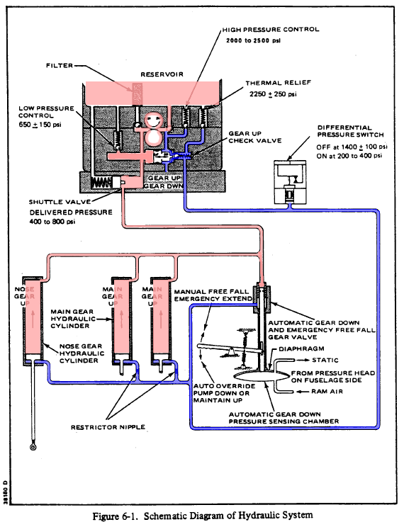
Figure 6-1 from the service manual is a hydraulic schematic for the landing gear hydraulic system on the Piper Lance II (PA32RT-300 and 300T). The same diagram, but with fewer notes, can be found in the Pilot’s Operating Handbook (POH). It is Figure 7-7 on page 7-8 of this aircraft’s version.

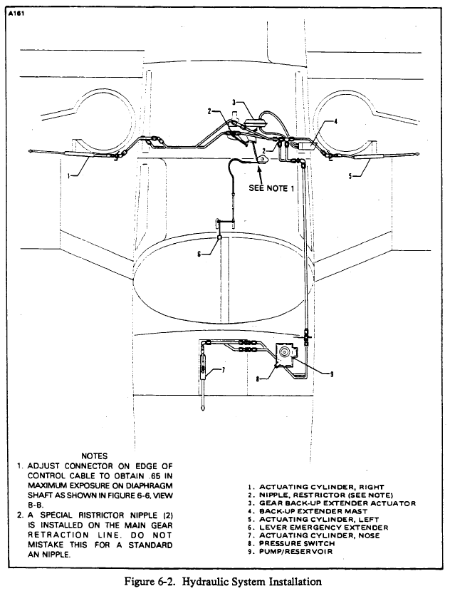
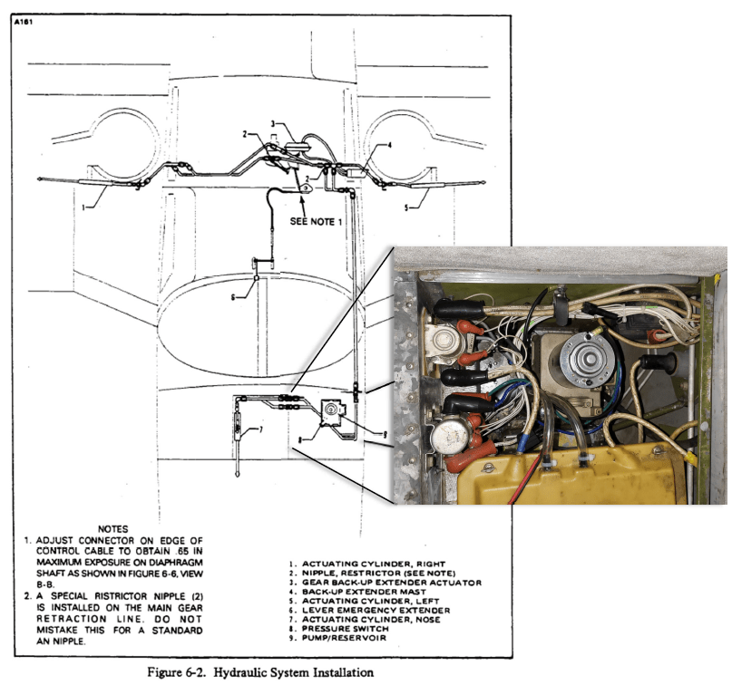
Figure 6-2 from the Service Manual shows the physical location of the hydraulic components.
Hydraulic Power Pack
They hydraulic power pack (Piper P/N 96671-02) is manufactured by Prestolite (Prestolite P/N HYC550). It is made up of an electric motor, hydraulic reservoir, and a pump/valve body. The power pack is located under the floor of the nose baggage compartment.
Gear Up
The figure below shows the hydraulic schematic color coded for the gear transitioning to the up position.

The pump is activated so that the top gear of the pump rotates clockwise. The ball on the suction side falls away from its seat allowing fluid from the reservoir to enter the left side of the pump while the pressure developed on the discharge of the pump holds the ball on the discharge side against its seat.
The High Pressure Control Valve regulates the discharge pressure to 2,000 – 2,500 psi by relieving excess pressure back to the reservoir. However, we will see that the operating pressure of the system in this installation is much lower and this valve should never open.
The shuttle valve below the pump is forced to the gear up position by the pump pressure and the pressure also opens this gear up check valve which allows the pump to pressurize the gear up side of the system.

The Differential Pressure Switch on the discharge of the pump turns off the pump when the pressure reaches 1,400 psi. Note that this is lower than the 2,000 – 2,500 psi regulated by the High Pressure Control Valve. The Differential Pressure Switch will turn the pump on again if the pressure falls to 400 – 200 psi. The Lance landing gear has no uplocks; the gear is held in the up position by hydraulic pressure alone. If there is a leak in the system and the pressure falls, the pump will reactivate to ensure that the gear remains in the fully up position.
The return fluid path is highlighted in blue. The fluid from the unpressurized side of the gear hydraulic cylinders through a shuttle valve. This shuttle valve remains in this position as long as the low pressure side of the power pack is below 400 – 800 psi.
Gear Down
Each of the three gear have springs installed that are in constantly trying to pull the gear into the down position and it is only hydraulic pressure that maintains the gear in the up position. In the next section, we will see that these springs provide for deploying the landing gear in an emergency, when hydraulic power is not available. Although the hydraulic system does provide hydraulic pressure to deploy the gear, the majority of deploying force is from the springs and the gear will not operate normally without this spring force.
The figure below has been color coded to show the hydraulic flow path and pressure when the gear is transitioning to the down position.
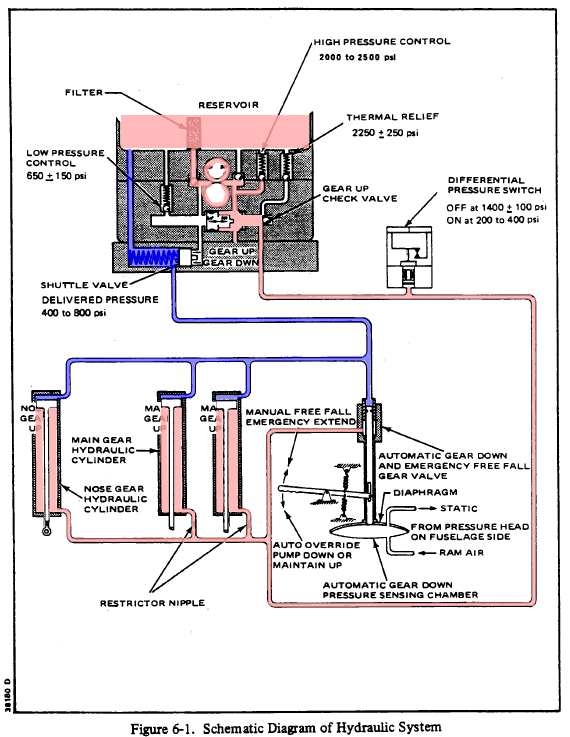
The pump is activated so that the top gear of the pump rotates counterclockwise. The ball on the suction side falls away from its seat allowing fluid from the reservoir to enter the right side of the pump while the pressure developed on the discharge of the pump holds the ball on the discharge side against its seat. This pressurizes the low pressure side of the power pack, including the Low Pressure Control Valve which relieves express pressure back to the reservoir to maintain the pressure to 400 – 800 psi.
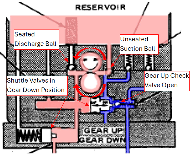
The shuttle valve below the pump is forced to the gear down position by the pump pressure and the pressure also opens this gear up check valve which allows the pump to pressurize the gear up side of the system. This shuttle valve has an extrusion that opens the Gear Up Check Valve which open the flow path for fluid from the hydraulic actuators on each gear to return to the hydraulic reservoir. This depressurizes the gear up side of the landing gear actuators and gear extension begins because of the spring loading on the gear.
The shuttle valve mounted on the bottom of the power pack is forced open by the hydraulic pressure, allowing the pressure to be applied to the hydraulic actuators on the landing gear, which forces the gear into the down position.
As noted before, the shuttle valve under the pump has an extrusion that pushes the Gear Up Check Valve off its seat. This depressurizes the gear up side of the hydraulic actuators. Note that the fluid returning form the actuators goes to the pump suction, not the reservoir.
Here are the they hydraulic schematics in the gear up and gear down positions side-by-side for comparison.